

Digital I/O Page
This content is for the 1.0.0 version. Switch to the latest version for up-to-date documentation.
The Digital I/O page monitors the digital inputs and drives the digital outputs on platforms that have digital I/O (the CQ40 series). On hardware without digital I/O, such as the CQ20, the page is greyed out. This page covers the app itself; for the connector pinout and per-channel wiring, see Digital I/O.
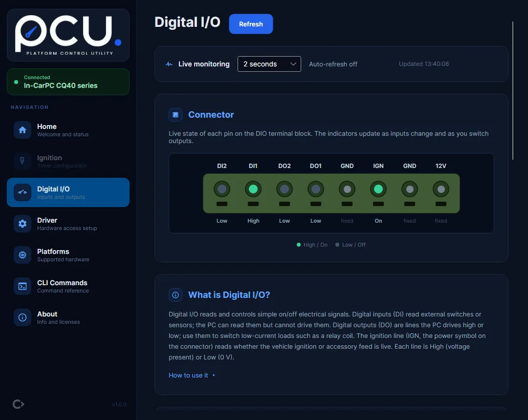
The connector diagram
Section titled “The connector diagram”The “Connector” card draws the DIO terminal block and lights each pin with its live state: green for High / On, grey for Low / Off. The full pin assignment is on Digital I/O.
The “What is Digital I/O?” card summarises the channels: inputs and the ignition line are read-only, and outputs are low-current, so drive a relay coil rather than the load directly. The electrical detail is on Digital I/O.
Live monitoring
Section titled “Live monitoring”The “Live monitoring” bar sets how often pcu re-reads the inputs and ignition line. Pick an interval from the dropdown (“Off”, “1 second”, “2 seconds”, “5 seconds”, “10 seconds”, or “30 seconds”; it defaults to 2 seconds). The label on the right shows “Updated HH:mm:ss” after each read. Use “Refresh” for a one-off full read. Inputs and the ignition line are read-only; only outputs can be changed.
Reading inputs
Section titled “Reading inputs”The “Digital Inputs” card lists each input (DI1, DI2) with a live “High” or “Low” badge and example uses. The “Ignition Line” card shows the ignition or accessory sense line as “On” or “Off”. These reflect what the connected switches and sensors are doing; the app cannot drive them.
Switching an output
Section titled “Switching an output”To turn an output on or off (for example DO1):
- On the “Digital Outputs” card, find “DO1”.
- Flip its toggle.
- In the confirmation dialog, check the change and select “Confirm”. The dialog is titled “Confirm Output Write” and reads, for example, “Set DO1 = High?”. It also reminds you that “Digital outputs drive connected hardware (relays, switches, lamps).”
- pcu writes the output, reads it back, and shows “DO1 set High - verified” once the hardware confirms it.
Every output change is confirmed and read back, so the state shown is the verified hardware state.